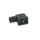
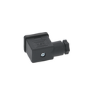
Details
The female voltage terminal slots are spaced at 12 mm from left to right and the center ground wire terminal slot is 12 mm above these. These are not the same as the flow meter connectors, part V_377. The inner core can be removed and rotated to facilitate the position of the terminal slots in the desired orientation.
Loosen the fixing screw holding the original connector to the solenoid. Remove the connector from the solenoid coil. Remove the rubber moisture protector. Loosen and draw back the wire restraint nut. Using a small straight screw driver, gently pry the center insert out (there is a small slot to insert the screwdriver into). Note the position and placement of your original wiring (wire color and if left or right of ground) and write it down or take a picture. Loosen the small wire fixing screws on the insert. Remove the original insert, body and wire restaint nut.
Replacement:
Feed the wires through the center of the new wire restraint nut and in to and through the body of the connector. Pull as much wire as is needed to comfortably be able to secure the wires with the small screws on the inside of the new insert. Secure the wires in their original position with the small screws. Draw the wiring back out of the connector at the same time as you press the insert back into place, noting that the ground terminal slot is also in it's original orientation. Slide the wire restraint back to the body and tighten it down. Replace the moisture protector. Press the connector back on to the solenoid coil and tighten the fixing screw.
Customer Reviews
Attention CA Residents: Prop 65 Warning
WARNING: This product can expose you to chemicals including lead, which are known to the State of California to cause cancer, birth defects, or other reproductive harm. For more information, go to www.p65warnings.ca.gov.


